Two-dimensional vector graphics (loops)—plotting two physiological variables simultaneously against each other without explicit time axes—transform continuous scalar data into real-time phase portraits of respiratory system mechanics. In modern mechanical ventilation, the Dynamic Pressure-Volume ($P$-$V$) Loop and the Dynamic Flow-Volume ($F$-$V$) Loop provide instantaneous bedside insight into static and dynamic compliance, airway resistance, dynamic hyperinflation, alveolar recruitment, regional overdistension, and patient-ventilator dyssynchrony.
+-------------------------------------------------------------------------+
|                    VENTILATOR VECTOR LOOPS AT A GLANCE                  |
+---------------------+-----------------------+---------------------------+
| Loop Type           | Axes (Y vs X)         | Primary Clinical Utility  |
+---------------------+-----------------------+---------------------------+
| Pressure-Volume     | Tidal Volume ($V$)    | Dynamic/static compliance,|
| ($P$-$V$) Loop      | vs Airway Press ($P$) | recruitment (LIP),        |
|                     |                       | overdistension (UIP/beak) |
+---------------------+-----------------------+---------------------------+
| Flow-Volume         | Airflow ($\dot{V}$)   | Airway resistance, dynamic|
| ($F$-$V$) Loop      | vs Tidal Volume ($V$) | flow limitation, secretions|
|                     |                       | auto-PEEP, circuit leaks  |
+---------------------+-----------------------+---------------------------+
The Dynamic Pressure-Volume ($P$-$V$) Loop
The Pressure-Volume ($P$-$V$) loop displays airway opening pressure ($P_{aw}$, $\text{cmH}_2\text{O}$) on the horizontal X-axis and delivered/exhaled lung volume ($V$, $\text{mL}$) on the vertical Y-axis. The loop traces a continuous closed trajectory throughout the respiratory cycle.
MANDATORY VENTILATION P-V LOOP:
Volume (mL)
  ^
VT|                .-'""'-. <--- Upper Inflection Point (UIP) / Overdistension
  |             .-'        \
  |          .-'            \  <--- Expiratory Limb
  |       .-' (Inspiration)  \
  |    .-'                    \
  | .-' <--- Lower Inflection  \
  |/         Point (LIP)        \
  +------------------------------\---------> Pressure (Paw, cmH2O)
  0          PEEP                 PIP
1. Loop Directionality and Work of Breathing
The direction in which the loop traces provides immediate insight into the energetic source driving gas exchange:
- Mandatory (Machine-Delivered) Breaths (Clockwise Direction):
- During positive-pressure mandatory inflation (VCV or PCV), airway pressure increases concurrently with lung volume expansion.
- The inspiratory limb moves upward and to the right; the expiratory limb returns downward and to the left, creating a clockwise trajectory.
- The total area enclosed within the loop reflects the total mechanical energy delivered by the ventilator to overcome respiratory system resistive and viscoelastic forces during inspiration.
- Spontaneous (Patient-Driven) Breaths (Counter-Clockwise Direction):
- During unassisted spontaneous inspiration, diaphragm contraction decreases pleural and alveolar pressure below atmospheric or PEEP baseline while volume expands, moving the inspiratory limb upward and to the left.
- The loop traces in a counter-clockwise trajectory, where the enclosed area directly represents the patient's physiological inspiratory work of breathing ($WOB_{pt}$).
- Assisted / Supported Breaths (Figure-of-8 Configuration):
- In assisted mechanical breaths (e.g., patient-triggered Volume Control or Pressure Support Ventilation), the breath initiates with an initial leftward/counter-clockwise deflection reflecting the patient's triggering effort (muscular pressure, $P_{mus}$).
- Once the ventilator triggers and delivers positive-pressure flow, the loop reverses direction into a clockwise trajectory.
- A prominent leftward "triggering belly" signifies high patient work of breathing, trigger asynchrony, or inadequate trigger sensitivity.
       MANDATORY BREATH                 SPONTANEOUS BREATH               ASSISTED BREATH
          (Clockwise)                   (Counter-Clockwise)              (Figure-of-8)
     Volume                           Volume                           Volume
       ^                                ^                                ^
       |       /|                       |   |\                           |     /|
       |      / |                       |   | \                          |    / |
       | (Insp)|(Exp)                   |(Exp)|(Insp)                    |   /  |(Exp)
       |    /   |                       |   |   \                        |  /   |
       |   /    |                       |   |    \                       |_/__  |
       |  /_____|                       |   |_____\                      |/   \ | (Insp)
       +----------> Paw                 +----------> Paw                 +----------> Paw
          PEEP   PIP                       PEEP   PIP                     Trig  PEEP PIP
2. Compliance Slope and Pathological Shifts
The overall orientation of the dynamic $P$-$V$ loop reflects the dynamic compliance of the total respiratory system ($C_{dyn}$):
$$C_{dyn} = \frac{V_T}{P_{peak} - PEEP}$$In contrast, a quasi-static line drawn between the end-expiratory starting point $(PEEP, 0)$ and the end-inspiratory static plateau coordinate $(P_{plat}, V_T)$ defines the static compliance chord:
$$C_{stat} = \frac{V_T}{P_{plat} - PEEP_{tot}} = \frac{V_T}{\Delta P}$$ PATHOLOGICAL COMPLIANCE SHIFTS ON P-V LOOP
Volume (mL)
^
| / <--- Normal Compliance (Crs ~ 50-80 mL/cmH2O)
| / .-' <--- High Compliance / Emphysema (Shifted Left/Steeper)
| / /
| //
| // .-' <--- Low Compliance / ARDS / Fibrosis (Shifted Right/Flatter)
| // .-'
| ///'
| //'
+--//----------------------------------------------------------> Pressure (Paw)
PEEP
- Decreased Compliance (Rightward / Downward Flattening):
- Seen in Acute Respiratory Distress Syndrome (ARDS), severe cardiogenic pulmonary edema, tension pneumothorax, pulmonary fibrosis, pleural effusions, and chest wall rigidity / abdominal compartment syndrome.
- The loop lays flat along the horizontal axis, requiring substantial driving pressure ($\Delta P$) to achieve modest tidal volume excursions.
- Increased Compliance (Leftward / Upward Steepening):
- Seen in advanced pulmonary emphysema and chronic obstructive pulmonary disease (COPD) with loss of alveolar elastic recoil.
- The loop rises steeply with minimal pressure changes.
3. Inflection Points, Alveolar Dynamics, and Hysteresis
The quasi-static or low-flow dynamic $P$-$V$ loop exhibits a sigmoidal ("S-shaped") configuration in heterogeneously injured lungs (e.g., ARDS).
                      SIGMOIDAL P-V LOOP AND INFLECTION POINTS
  Volume (mL)
    ^
    |                                   .-'""'-. <--- "Beaking" / Overdistension Zone
    |                   UIP --------> .-'       :
    |                              .-'          : <--- Linear Compliance Zone
    |                           .-'             :      (Safe Ventilation Window)
    |                        .-'                :
    |         LIP --------> .-'                 :
    |                    .-'                    :
    |   De-recruitment .-'                      :
    |   Atelectrauma   |                        :
  0 +------------------+------------------------+------------------> Pressure (Paw)
    0                 PEEP                     Pplat
Lower Inflection Point (LIP)
- Definition: The pressure threshold on the early inspiratory limb where the slope ($dV/dP$) undergoes an abrupt upward transition from flat (high elastance) to steep (high compliance).
- Physiological Mechanism: Reflects the critical opening pressure required to overcome surface tension and adhesive forces in collapsed, fluid-filled, dependent alveolar units. Below the LIP, lung units undergo cyclic opening and closing (atelectrauma).
- Clinical Implication: Titrating extrinsic positive end-expiratory pressure ($PEEP$) $2\text{--}3\text{ cmH}_2\text{O}$ above the LIP maintains end-expiratory alveolar patency, eliminates cyclic tidal collapse, and minimizes shear stress.
Upper Inflection Point (UIP)
- Definition: The pressure threshold on the late inspiratory limb where compliance abruptly decreases, characterized by a rightward flattening of the curve ($dV/dP$ decreases).
- Physiological Mechanism: Marks the transition from alveolar recruitment to structural overstretching (volutrauma / barotrauma) as lung units reach their maximal anatomical volume limit.
- Clinical Implication: The upper limit of tidal ventilation ($P_{plat}$ or peak dynamic distension) must remain below the UIP to prevent alveolar rupture, microvascular stretch injury, and biotrauma.
The "Duck-Bill" or "Beaking" Sign
- Morphology: In Volume-Controlled Ventilation with excessive tidal volume or insufficient elastance capacity (the "baby lung" of ARDS), the terminal portion of the inspiratory $P$-$V$ loop hooks sharply to the right without meaningful volume gain, resembling the beak of a duck or bird.
- Pathophysiology: Severe dynamic alveolar overdistension. Incremental ventilator work is entirely dissipated as excessive tissue stress rather than productive gas volume.
- Immediate Bedside Action: Promptly reduce tidal volume ($V_T$) to $4\text{--}6\text{ mL/kg}$ predicted body weight (PBW) or lower inspiratory pressure until the beak disappears and the terminal loop slope aligns with the linear compliance zone.
Hysteresis and Lung Recruitability
- Definition: The area enclosed between the inspiratory and expiratory limbs of the $P$-$V$ curve.
- Mechanism: The lung requires higher pressure to open during inspiration than to remain open during expiration at identical lung volumes. Hysteresis arises from surfactant redistribution, tissue viscoelastic stress relaxation, and opening/closing pressure discrepancies.
- Recruitability Assessment: A broad hysteresis area on a low-flow $P$-$V$ maneuver signifies significant recruitable lung tissue; a narrow, collapsed loop indicates fixed, non-recruitable consolidation or fibrotic destruction.
The Dynamic Flow-Volume ($F$-$V$) Loop
The Flow-Volume ($F$-$V$) loop continuously plots airflow ($\dot{V}$, $\text{L/min}$ or $\text{L/s}$) on the vertical Y-axis against delivered/exhaled volume ($V$, $\text{mL}$) on the horizontal X-axis.
- By standard convention in intensive care mechanical ventilators, inspiratory flow is plotted above the horizontal zero-flow baseline, and expiratory flow is plotted below the horizontal baseline.
- The loop begins and ends at the zero-flow, zero-volume intersection coordinate $(0, 0)$.
                     NORMAL FLOW-VOLUME LOOP GEOMETRY
  Flow (L/min)
    ^
    |          +--------------------+ <--- Constant Inspiratory Flow (VCV Square)
    |          |   (Inspiration)    |
    |          |                    |
    |          |                    |
  0 +----------+--------------------+------------------------> Volume (mL)
    |          \                   /  0                      VT
    |           \                 /
    |            \               / <--- Rapid, Linear Expiratory Decay
    |             \             /       (Passive Elastic Recoil)
    |              \           /
-Pk |               \_________/ <--- Peak Expiratory Flow (PEFR)
1. Normal Loop Morphologies
- Volume-Controlled Ventilation (VC-CMV):
- Inspiratory Limb: Rectangular / box-shaped when using constant square flow (flow steps instantly to set peak, remains flat across volume delivery, then drops to zero at $V_T$). In decelerating ramp flow, it displays a right-triangle profile.
- Expiratory Limb: Rises immediately to a sharp, negative Peak Expiratory Flow Rate (PEFR), followed by a smooth, near-linear or single-exponential decay back to $(0, 0)$ as elastic recoil dissipates.
- Pressure-Controlled Ventilation (PC-CMV):
- Inspiratory Limb: Triangular profile. Flow peaks instantaneously at the onset of pressurization and decays linearly/exponentially toward zero as volume approaches $V_T$.
- Expiratory Limb: Identical passive exponential decay driven by respiratory system elastance and resistance.
2. Pathological $F$-$V$ Loop Configurations
  OBSTRUCTIVE (SCOOPED)               CIRCUIT / CUFF LEAK                SECRETIONS / SAWTOOTH
   Flow                                Flow                                Flow
     ^                                   ^                                   ^
     |    +-------+                      |    +-------+                      |   /\_/\_/\
   0 +----+-------+-----> Vol          0 +----+-------+-----> Vol          0 +---+-------+-----> Vol
     |     \     /                       |     \     /                       |    \~~~~~/ <--- Sawtooth
     |      \ _ / <--- Scooping /        |      \   / <--- Fails to          |     \___/       flutter
 -Pk |       V         Air Trapping  -Pk |       \_/       reach 0 (Leak) -Pk|
A. Obstructive Airway Disease and Expiratory Scooping
- Visual Morphology:
- Depressed peak expiratory flow rate (PEFR).
- Deep inward concavity ("scalloping" / "scooped-out" coving) of the mid-to-late expiratory limb.
- Prolonged expiratory phase where the tail fails to reach zero volume before the subsequent breath initiates.
- Pathophysiology: Dynamic compression of small airways during exhalation (expiratory flow limitation, EFL). Upstream airway resistance increases precipitously, causing severe gas deceleration and dynamic hyperinflation (auto-PEEP).
- Bedside Detection: The horizontal distance between where the expiratory limb is cut off by the next breath and the zero baseline represents the volume trapped per cycle.
B. The "Sawtooth" Pattern
- Visual Morphology: Prominent, high-frequency, jagged oscillations/fluctuations decorating the inspiratory and/or expiratory flow limbs.
- Pathophysiology:
- Accumulation of liquid secretions/mucus in the proximal trachea or large airways.
- Water condensation pooling in the ventilator corrugated tubing circuit (circuit rainout).
- Intermittent fluttering of an endotracheal tube cuff or compliant airway wall.
- Actionable Intervention: Perform targeted endobronchial suctioning; inspect and drain dependent water traps in the ventilator breathing circuit.
C. Air Leaks (Incomplete Expiratory Loop)
- Visual Morphology: The expiratory limb terminates abruptly into the horizontal axis significantly to the right of the zero-volume baseline, leaving an open, unclosed loop.
- Pathophysiology: The exhaled volume returned to the ventilator flow sensor is substantially lower than the volume delivered during inspiration ($V_{TE} < V_{TI}$).
- Calculated Leak: $$\text{Leak Volume} = V_{TI} - V_{TE}$$
- Etiologies:
- Endotracheal tube cuff deflation, rupture, or malposition above the vocal cords.
- Circuit disconnection, unseated humidification chamber, or cracked water trap.
- Large bronchopleural or tracheoesophageal fistula with chest tube drainage loss.
Multimodal Comparative Analysis
+----------------------------------------------------------------------------------------------------+
|                      VECTOR LOOP PATHOLOGY & INTERVENTION MATRIX                                   |
+----------------------+-----------------------------+-----------------------+-----------------------+
| Graphic Abnormality  | Loop Type & Specific Sign   | Underlying Mechanism  | Targeted Clinical     |
|                      |                             |                       | Management            |
+----------------------+-----------------------------+-----------------------+-----------------------+
| Duck-bill / Beaking  | P-V Loop: Terminal          | Alveolar overstretch; | Reduce tidal volume;  |
| Sign                 | rightward flattening        | compliance exhaustion | lower PIP/Pplat target|
|                      | (dP/dV approaches infinity) | at end-inspiration    | below UIP (< 28-30)   |
+----------------------+-----------------------------+-----------------------+-----------------------+
| Rightward Slope      | P-V Loop: Decreased slope   | Loss of functional    | Recruit lung; titrate |
| Flattening           | of static/dynamic axis      | residual capacity; low| PEEP above LIP; treat |
|                      | ($dV/dP$ reduced)           | compliance (ARDS, ed.)| edema/pneumothorax    |
+----------------------+-----------------------------+-----------------------+-----------------------+
| Counter-Clockwise    | P-V Loop: Leftward belly /  | High patient muscular | Increase flow/support;|
| Inspiratory Deflect. | loop reversal (Fig.-of-8)   | effort ($P_{mus}$)    | optimize trigger sens;|
|                      |                             | and flow starvation   | assess sedation depth |
+----------------------+-----------------------------+-----------------------+-----------------------+
| Expiratory Scooping  | F-V Loop: Deep inward       | Severe bronchospasm;  | Deliver bronchodilator|
| & Truncation         | concavity + auto-PEEP cut   | dynamic small airway  | increase TE; lower RR;|
|                      |                             | collapse (COPD/asthma)| titrate PEEP to 80% iP|
+----------------------+-----------------------------+-----------------------+-----------------------+
| Jagged "Sawtooth"    | F-V Loop: High-frequency    | Secretions in central | Perform airway        |
| Oscillations         | sinusoidal flutter on flow  | airways; circuit      | suctioning; drain     |
|                      | tracing                     | water condensation    | circuit water traps   |
+----------------------+-----------------------------+-----------------------+-----------------------+
| Unclosed Expiratory  | F-V Loop & P-V Loop: Fail   | Gas escape from       | Inflate ETT cuff to   |
| Baseline Step        | to return to origin (0, 0)  | system ($V_{TE} < V_{TI}$)| 20-30 cmH2O; check    |
|                      |                             |                       | circuit; chest tube   |
+----------------------+-----------------------------+-----------------------+-----------------------+
Peer-Reviewed Clinical Graphic Artifact
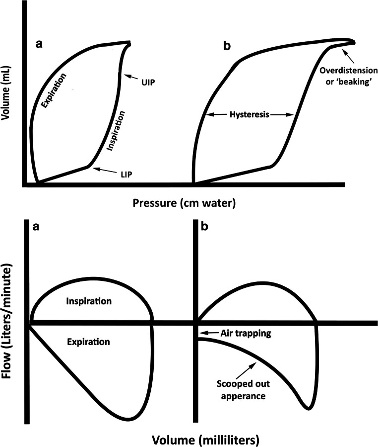 Figure 1: Morphological anatomy of dynamic and quasi-static ventilator vector loops. (Left Panel) Pressure-Volume ($P$-$V$) loop illustrating the Lower Inflection Point (LIP, alveolar opening pressure), Upper Inflection Point (UIP, overdistension threshold), the safe linear compliance ventilation zone, terminal "beaking" caused by alveolar overstretch, and the physiological hysteresis loop enclosing inspiratory work. (Right Panel) Flow-Volume ($F$-$V$) loop demonstrating normal rectangular inspiratory and linear expiratory profiles versus obstructive airflow limitation with prominent expiratory scooping, reduced peak expiratory flow (PEFR), and gas trapping (auto-PEEP). Provenance: Current Pediatrics Reports 2021; 9(1):1–10; DOI: 10.1007/s40124-020-00235-4 / PMC7782574 (CC-BY 4.0).
Real-Time Clinical Titration Protocols
1. PEEP Optimization via the Lower Inflection Point (Open-Lung Strategy)
       PEEP TITRATION STRATEGY RELATIVE TO INFLECTION POINTS
  Volume
    ^
    |                      .-'""'-. <--- Danger: Overdistension Zone (UIP)
    |                   .-'
    |                .-' <--- Target Tidal Ventilation Window:
    |             .-'         PEEP set > LIP; Peak/Plat set < UIP
    |          .-'
    |       .-' <--- Target PEEP = LIP + (2 to 3 cmH2O)
    |    .-' <--- LIP: Alveolar Opening Pressure
    | .-'
  0 +-+-----+----------------------------------------------------------> Pressure
    0       PEEP (Set)
- Identification of Opening Pressure:
- Perform a low-flow ($< 10\text{ L/min}$ or $3\text{--}5\text{ L/min}$) quasi-static inflation maneuver or a decremental PEEP trial while observing the $P$-$V$ loop.
- Pinpoint the LIP where the tangent of the curve shifts upward.
- Setting Protective Baseline:
- Set baseline $PEEP = \text{LIP} + 2\text{--}3\text{ cmH}_2\text{O}$.
- This keeps end-expiratory alveolar volume above the closing pressure threshold, preventing recurrent cyclic collapse (atelectrauma) and reducing shear stress during repetitive cycles.
2. Preventing Overdistension via the Upper Inflection Point and Beak Elimination
- Identifying Overstretch:
- Monitor the inspiratory limb of the dynamic $P$-$V$ loop during volume delivery.
- If the curve deviates to the right with a sharp horizontal flattening ("duck-bill" or "beak"), compliance at the end of the breath is approaching zero.
- Titration Protocol:
- Reduce tidal volume stepwise in decrements of $0.5\text{--}1.0\text{ mL/kg}$ PBW until the beak disappears.
- Maintain static plateau pressure $P_{plat} < 28\text{--}30\text{ cmH}_2\text{O}$ and driving pressure $\Delta P \le 14\text{ cmH}_2\text{O}$.
                 BEAK ELIMINATION TITRATION SEQUENCE
  Volume                               Volume
    ^                                    ^
    |             .-'""'-._ (Beak)       |             .-'""'-. (Linear compliance,
    |          .-'                       |          .-'          no overdistension)
    |       .-'                          |       .-'
    |    .-'                             |    .-'
    +---'-------------------------> Paw  +---'-------------------------> Paw
       High VT (Overdistension)              Optimized VT (Lung-Protective)
3. Evaluating Bronchodilator Responsiveness via the $F$-$V$ Loop
The dynamic $F$-$V$ loop provides immediate visual and quantitative confirmation of bronchodilator efficacy without waiting for blood gas results:
               PRE- VS POST-BRONCHODILATOR F-V LOOP DYNAMICS
  Flow (L/min)
    ^
    |          +--------------------+
    |          |    Inspiration     |
    |          |                    |
  0 +----------+--------------------+------------------------> Volume (mL)
    |          \                   /
    |           \ ______          /
    |            \      '''---   / <--- Pre-Bronchodilator (Severe Scooping)
    |             \   _--'      /
    |              \ /         / <--- Post-Bronchodilator (Area Expansion & PEFR ↑)
    |               V         /
-Pk |               \________/
- Baseline Assessment:
- Note baseline Peak Expiratory Flow Rate (PEFR), degree of expiratory concavity, and end-expiratory flow truncation (auto-PEEP).
- Post-Intervention Verification (Inhaled Beta-2 Agonist / Anticholinergic):
- Positive Response Criteria:
- $\ge 15\text{--}20\%$ increase in Peak Expiratory Flow Rate (PEFR).
- Elimination or outward rounding of the expiratory scoop (expanded loop envelope).
- Return of the expiratory flow limb to true zero baseline prior to the subsequent inspiration, confirming resolution of dynamic hyperinflation.
- Positive Response Criteria:
Practical Bedside Pearls
Dynamic vs Static P-V Loops: Dynamic $P$-$V$ loops measured during normal inspiratory flow include resistive pressure dissipation ($\dot{V} \times R_{aw}$), making the loop broader. A true compliance assessment requires either a low-flow inflation maneuver ($< 5\text{ L/min}$) or an end-inspiratory occlusion pause to derive true static mechanics.
The Spontaneous "Triggering Belly": On a Pressure-Volume loop during assisted modes, a large leftward deflection below baseline PEEP indicates excessive patient triggering work. When observed, immediately evaluate for trigger sensitivity mismatch, high auto-PEEP (which imposes an unmeasured threshold load), or severe flow starvation.
Artifactual Sawtooth Patterns: Before administering bronchodilators or performing aggressive suctioning for a sawtooth flow pattern, inspect the ventilator tubing! Circuit rainout (water condensation) vibrating with gas flow is the single most common cause of false-positive sawtooth loops.
Key Takeaways
- Directionality reveals breath origin: Clockwise loops reflect positive-pressure mandatory machine work; counter-clockwise loops reflect spontaneous patient work; figure-of-8 loops reflect assisted patient-triggered breaths.
- Inflection points establish safe mechanical boundaries: Set PEEP above the Lower Inflection Point (LIP) to prevent atelectrauma; maintain peak distending pressure below the Upper Inflection Point (UIP) to prevent volutrauma.
- The "Duck-Bill" sign mandates tidal reduction: Terminal rightward flattening of the $P$-$V$ loop confirms dangerous alveolar overdistension and requires immediate downward titration of tidal volume or inspiratory pressure.
- Flow-Volume loops diagnose airway dynamics: Expiratory scooping quantifies dynamic airflow obstruction; sawtooth flutter identifies secretions or condensation; an unclosed loop confirms gas leaks.
- Real-time response tracking: Successful bronchodilator therapy or PEEP optimization produces immediate visual expansion of the $F$-$V$ loop envelope and normalization of the $P$-$V$ compliance slope.